【Rust】Creating a Table Lamp using a Raspberry Pi Learning Kit
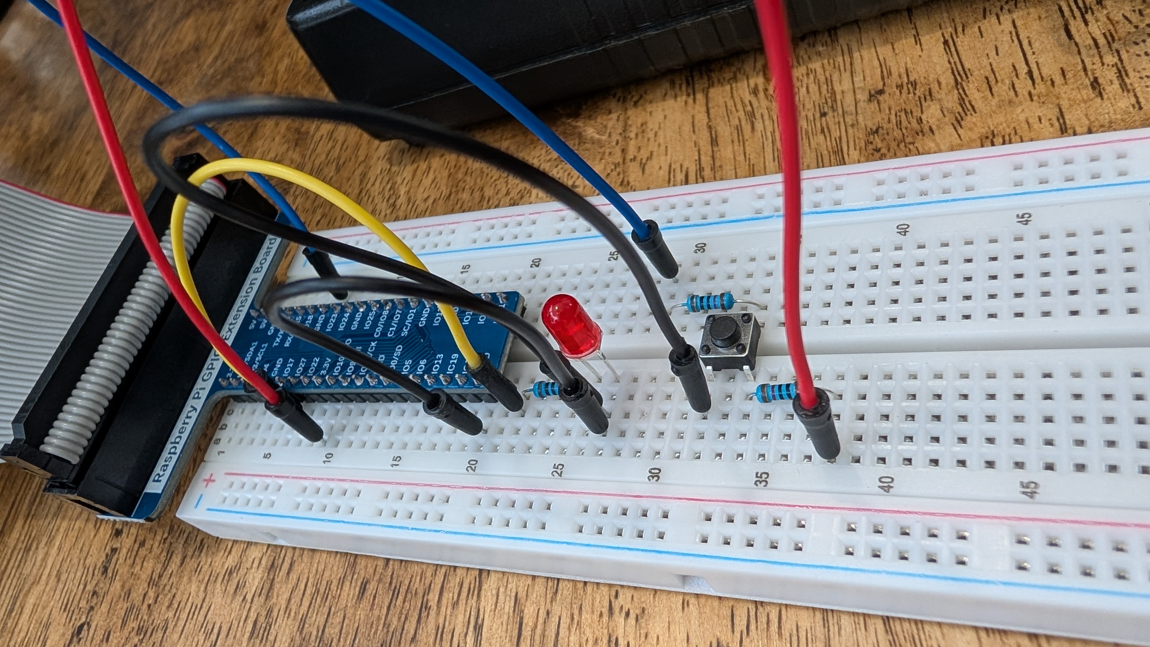
Table of Contents
Overview
This article describes how to add a button to an LED blinking circuit and control its lighting using Rust. As before, we will use the material from Freenove. The kit can be purchased on amazon, but since the parts are generic, please procure them by any method you prefer.
Circuit
The components used are as follows:
- 220Ω resistor x1
- 10kΩ resistor x2
- Tact switch x1
- LED
Wiring and circuit diagrams are available in 2.1.3. Circuit at the link. Please build the circuit according to the diagrams.
Code
We will write the code by adding rppal and ctrlc with cargo.
ButtonSwitch
An infinite loop is used to determine whether the level of GPIO18 is HIGH or LOW, depending on whether power is supplied to it. When the button is pressed, HIGH and LOW switch, and the LED pin is controlled to HIGH/LOW accordingly.
use rppal::gpio::{Gpio, Level};
use std::error::Error;

const LED_PIN: u8 = 17;
const BTN_PIN: u8 = 18;

fn main() -> Result<(), Box<dyn Error>> {
    println!("Program is starting...");
    let gpio = Gpio::new()?;
    let mut led_pin = gpio.get(LED_PIN)?.into_output();
    let btn_pin = gpio.get(BTN_PIN)?.into_input();
    // Terminate when Ctrl+C is pressed
    let running = Arc::new(AtomicBool::new(true));
    let r = running.clone();
    ctrlc::set_handler(move || {
        r.store(false, Ordering::SeqCst);
    })?;
    loop {
        if btn_pin.is_low() {
            // led_pin.set_high();
            led_pin.write(Level::High);
            println!("Button is pressed, led turned on >>>");
        } else {
            // led_pin.set_low();
            led_pin.write(Level::Low);
            println!("Button is released, led turned off <<<");
        }
    }
}
TableLamp
While ButtonSwitch was designed to turn on the power only while the switch was pressed, TableLamp is a code that toggles ON/OFF each time the button is pressed. btn_pin.poll_interrupt(true, Some(Duration::from_millis(1)))? is used to determine if the button has been pressed. If the button is pressed, it checks if the LED pin is in a LOW state and controls the power ON/OFF.
use rppal::gpio::{Gpio, Level, Trigger};
use std::error::Error;
use std::sync::atomic::{AtomicBool, Ordering};
use std::sync::Arc;
use std::time::Duration;

const LED_PIN: u8 = 17;
const BTN_PIN: u8 = 18;

fn main() -> Result<(), Box<dyn Error>> {
    println!("Program is starting...");
    let gpio = Gpio::new()?;
    let mut led_pin = gpio.get(LED_PIN)?.into_output();
    let mut btn_pin = gpio.get(BTN_PIN)?.into_input();
    led_pin.set_low();
    // Button interrupt setting
    btn_pin.set_interrupt(Trigger::FallingEdge, None);
    // Terminate when Ctrl+C is pressed
    let running = Arc::new(AtomicBool::new(true));
    let r = running.clone();
    ctrlc::set_handler(move || {
        r.store(false, Ordering::SeqCst);
    })?;
    println!("Waiting for button press...");
    while running.load(Ordering::SeqCst) {
        if let Some(_) = btn_pin.poll_interrupt(true, Some(Duration::from_millis(1)))? {
            // Toggle LED state
            if led_pin.is_set_low() {
                led_pin.set_high();
                println!("Led turned on >>>");
            } else {
                led_pin.set_low();
                println!("Led turned off <<<\n");
            }
        }
    }
    println!("Program is finished.");
    btn_pin.clear_interrupt();
    led_pin.set_low();
    Ok(())
}
Demonstration
Only ButtonSwitch is demonstrated, but the operation is uploaded to X (twitter).
昨日の続き
— K (@rmc_km) June 1, 2025
ボタンのオンオフを検知して関数を実行する仕組みもあるようだけどライブラリ側にこってり書かれていそうでライブラリを呼び出す側からは仕組みが見えづらい雰囲気 pic.twitter.com/90yU0ydIXF
Summary
We have added button-controlled power to the LED blinking circuit. You should have understood that by using GPIO18 and a switch, you can change the state of the circuit and read the state in real time with a program. Also, depending on how the program is written, it can operate only while the button is pressed, or change its operation each time the button is pressed. The important point is that the operation changes even with the same circuit by simply modifying the program to suit the desired function. Since the operation can be changed by the program even with the same circuit, it is easy to adjust, so I thought that learning would be deepened by building a simple circuit and changing the software adjustments in various ways. Next time, we will implement more complex LED control using an LED light bar.


Loading comments...